Papers with Whittle Lab authors at ASME Turbo Expo, June 14-18 2010, Glasgow
The Impact of Real Geometries on Three-Dimensional Separations in Compressors
Martin N. Goodhand and Robert J. Miller
Paper GT2010-22246; Session WC-26-4; Wednesday 2:30pm-5:30pm
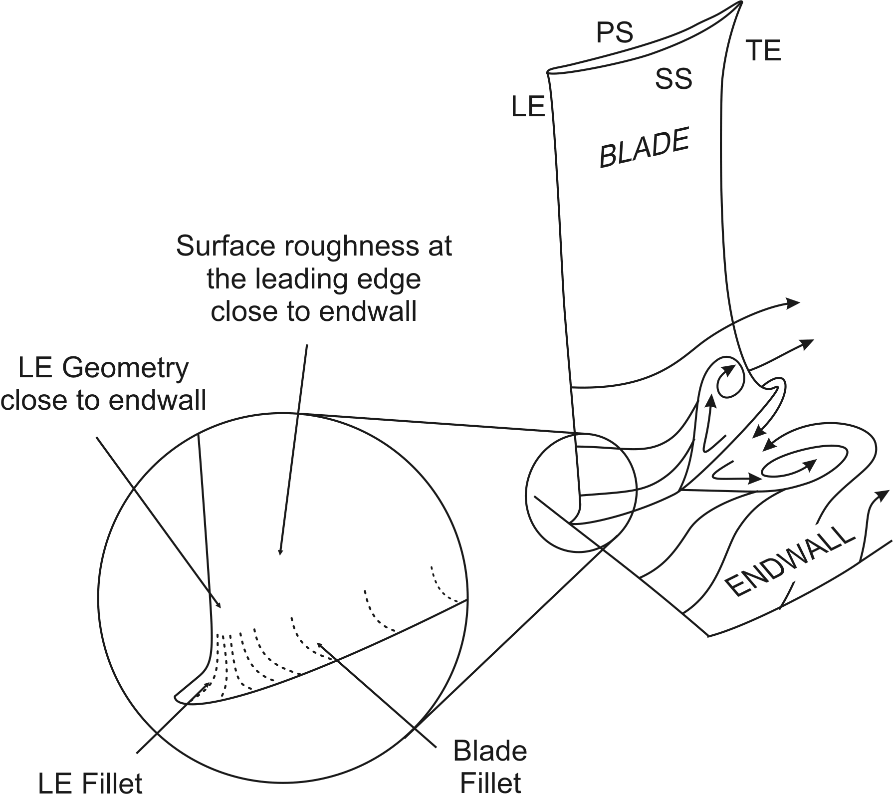
This paper considers the effect of small variations in leading edge geometry, leading edge roughness, leading edge fillet and blade fillet geometry on the three dimensional separations found in compressor blade rows. The detrimental effects of these separations have historically been predicted by correlations based on global flow parameters, such as blade loading, inlet boundary layer skew etc, and thus ignoring small deviations such as those highlighted above. In this paper it is shown that this may not to be the case and that certain, engine representative geometry deviations can have an effect equivalent to an increase in blade loading of 10%.
Experiments were performed at the stator hub of a low-speed, single-stage compressor. The results show that any deviation which causes suction surface transition to move to the leading edge over the first 30% of span will cause a large growth in the size of the hub separation, doubling its impact on loss. The geometry deviations that caused this, and are thus of greatest concern to a designer, are changes in leading edge quality and roughness around the leading edge, characteristic of an eroded blade.
Stability Enhancement by Casing Grooves: The Importance of Stall Inception Mechanism and Solidity
Tim Houghton and Ivor Day
Paper GT2010-22284; Session ThB-33-7; Thursday 10:15am-12:15pm
This paper concerns the optimisation of casing grooves and the important influence of stall inception mechanism on groove performance. Installing casing grooves is a well known technique for improving the stable operating range of a compressor, but the wide-spread use of grooves is restricted by the loss of efficiency and flow capacity. In this paper, laboratory tests are used to examine the conditions under which casing treatment can be used to greatest effect. The use of a single casing groove was investigated in a recently published companion paper. The current work extends this to multiple-groove treatments and considers their performance in relation to stall inception mechanisms. Here it is shown that the stall margin gain from multiple grooves is less than the sum of the gains if the grooves were used individually. By contrast, the loss of efficiency is additive as the number of grooves increases. It is then shown that casing grooves give the greatest stall margin improvement when used in a compressor which exhibits spike-type stall inception, while modal activity before stall can dramatically reduce the effectiveness of the grooves. This finding highlights the importance of being able to predict the stall inception mechanism which might occur in a given compressor before and after grooves are added. Some published prediction techniques are therefore examined, but found wanting. Lastly, it is shown that casing grooves can, in some cases, be used to remove rotor blades and produce a more efficient, stable and light-weight rotor.
Hybrid LES Approach for Practical Turbomachinery Flows: Part 1 - Hierarchy and Example Simulations
Tucker P. G., Eastwood S. , Klostermeier C., Jefferson-Loveday R., Tyacke J. and Liu Y.
Paper GT2010-23431; Session FC-29-6; Friday 2:30pm-5:00pm
Unlike Reynolds Averaged Navier Stokes (RANS) models which need calibration for different flow classes, LES (where larger turbulent structures are resolved by the grid and smaller modeled in a fashion reminiscent of RANS) offers the opportunity to resolve geometry dependent turbulence as found in complex internal flows - albeit at substantially higher computational cost. Based on the results for a broad range of studies involving different numerical schemes, LES models and grid topologies an LES hierarchy and hybrid LES related approach is proposed. With the latter, away from walls, no LES model is used, giving what can be termed Numerical LES (NLES). This is relatively computationally efficient and makes use of the dissipation present in practical industrial CFD programs. Near walls, RANS modeling is used to cover over numerous small structures, the LES resolution of which is generally intractable with current computational power. The linking of the RANS and NLES zones through a Hamilton-Jacobi equation is advocated. The RANS-NLES hybridization makes further sense for compressible flow solvers, where, as the Mach number tends to zero at walls, excessive dissipation can occur. The hybrid strategy is used to predict flow over a rib roughened surface and a jet impinging on a convex surface. These cases are important for blade cooling and show encouraging results. Further results are presented in a companion paper.
Hybrid LES Approach for Practical Turbomachinery Flows: Part 2 - Further Applications
Tucker P. G., Eastwood S. , Klostermeier C., H. Xia, Ray P., Tyacke J. and Dawes W. N.
Paper GT2010-23807; Session FC-29-6; Friday 2:30pm-5:00pm
A hybrid Large Eddy Simulation (LES) related technique is used to explore some key turbomachinery relevant flows. Near wall RANS modeling is used to cover over especially small scales, the LES resolution of which is generally intractable with current computational power. Away from walls, large eddy type simulation is used but with no LES model (NLES). Linking of the two model zones through a Hamilton-Jacobi equation is explored. The hybrid strategy is used to predict turbine and compressor endwall flows, flow around a fan blade section, jet flows and a cutback trailing edge. Also, application of NLES to the flow in an idealized high pressure compressor drum cavity is considered. Generally, encouraging results are found. However, challenges remain, especially for flows where transition modeling is important.
Predicting the Profile Loss of High-Lift Low Pressure Turbines
Coull, J.D. and Hodson, H.P.
Paper GT2010-22675; Session WA-27-4; Wednesday 8:00am-10:00am
The overall efficiency of Low Pressure (LP) turbines is largely determined by the two-dimensional profile loss, which is dominated by the contribution of the suction surface boundary layer. This boundary layer typically features a laminar separation bubble and is subjected to an inherently unsteady disturbance environment. The complexity of the flow behavior makes it difficult to numerically predict the profile loss. To address this problem, an empirical method is proposed for predicting the boundary layer integral parameters at the suction surface trailing edge, allowing the profile loss to be estimated.
Extensive measurements have been conducted on a flat plate simulation of the suction surface boundary layer. The disturbance environment of real machines was modeled using a moving-bar wake generator and a turbulence grid. From this dataset, empirically based methods have been formulated using physical principles for the prediction of the momentum thickness and shape factor at the suction surface trailing edge. The predictions of these methods may be used to estimate the profile loss of a given cascade, which achieves reasonable agreement with the available data.
By parameterizing the shape of the suction surface velocity distribution, the method is recast as a preliminary design tool. This may be used to guide the selection of the key design parameters (such as the blade loading and velocity distribution shape) and enables a reasonable estimation of the unsteady profile loss to be made at a very early stage of design.
To illustrate the capabilities of the preliminary design tool, different styles of velocity distribution are evaluated for fixed blade loading and flow angles. The predictions suggest that relatively "flat-top" designs will have the lowest profile loss, but good performance can also be achieved with front-loaded "peaky" distributions. The latter designs are more likely to have acceptable incidence tolerance.
Geometrical Uncertainty and Film Cooling: Fillet Radii
Montomoli F., Massini M, Salvadori S. and Martelli F.
Paper GT2010-22979; Session WA-9-5; Wednesday 8:00am-10:00am
This study presents an investigation of the impact of filleted edges variations on heat transfer. In real gas turbines, sharp edges are an approximation, because of manufacturing tolerances and/or geometrical modifications occurring during operation. The value of fillet radius is not exactly known a priori. It can be assumed that a specific radius occurs with a probability following a probabilistic distribution.
For this reason, the effect of variation of the filleted edge on internal channel of a film cooling configuration has been studied numerically using an in house solver. The hole exit is fan-shaped and the feeding duct axis and the main stream are perpendicular to each other. A response surface has been generated varying the internal Mach number of coolant and the pressure ratio range between coolant and main gas. Four fillets radii for the internal duct have been analysed, r/D=0.0-5%. A Gaussian distribution for the fillet radius has been assumed. Using the over mentioned distributions it is possible to obtain the probabilistic functions of corresponding discharge coefficient, Cd, and adiabatic effectiveness. The overall variation of Cd and effectiveness can be more than 10% the value without fillet. Furthermore the differences on Cd due the uncertainties on fillet radius are bigger than those obtained modifying the exit duct shape (i.e. from cylindrical to fanshaped).
This paper shows that the effect of variation of fillet radii must be included in numerical simulations. This has direct consequences on LES and DNS simulations, which normally include sharp corners or mean radii. A probabilistic approach must be included in the analysis of the results and the equivalent fillet radius assumed instead.
Analysis of the Effect of a Non-uniform Inlet Profile on Heat Transfer and Fluid Flow in Turbine Stages
Salvadori S, Montomoli F, Chana K, Martelli F, Povey T., Qureshi I.
Paper GT2010-23526; Session TC-33-2; Tuesday 2:30pm-5:30pm
This paper presents an investigation of the performance of the MT1 turbine evaluating the stage efficiency. In this work experimental data and CFD simulations are analysed and compared. These experimental investigations were carried out at the QinetiQ Turbine Test Facility (QTTF) based at Farnborough (UK). Experiments were conducted at full aero engine scale with a rotating high pressure (HP) transonic stage. Following an analysis of the datum stage with uniform inlet a hot spot with an intensity of 1.17 was introduced at the turbine inlet. Accurate area surveys of turbine inlet and exit flows and detailed measurements of the blade surfaces and end-walls were obtained. These results are analysed and compared with the unsteady numerical data obtained using the in-house HybFlow code developed at the University of Firenze.
Two aspects are highlighted: prediction confidence for state of the art computational fluid dynamics (CFD) and impact of real conditions on stator-rotor thermal loading. The value of efficiency obtained with the numerical analysis is compared with the experimental data and a 2% difference is found and discussed. A study of the flow field influence on the blade thermal load has also been detailed. It is shown that the hot streak migration mainly affects the rotor pressure side from 20% to 70% of the span. Here the Nusselt increases by a factor of 60% in comparison with uniform case. Furthermore, it has been found that a not uniform distribution is beneficial for the rotor tip, contrary to the results found in the open literature. One of the reasons explaining these differences is that a realistic temperature distribution that takes into account the combustor cooling is used at the stage inlet. The hot streak is affected by the pressure gradient across the tip gap but coolant near the casing is able to protect the blade tip from this hot gas. A design approach not taking into account these effects underestimates the rotor life near the tip and the thermal load at mid-span.
The Effect of an Upstream Compressor on a Non-Axisymmetric S-duct
Marios Karakasis, Edward Naylor, Rob Miller and Howard Hodson
Paper GT2010-23404; Session FB-26-8; Friday 10:15am-12:45pm
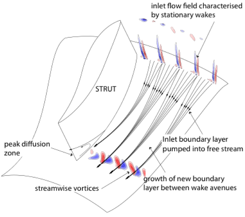
This paper considers the effect of an upstream compressor stage on a compressor inter-spool duct. The duct geometry must be fixed early in the engine design process, well before the design of the upstream stages. It is therefore important that the designer has a good physical insight into how engine representative inlet conditions affect the limits of the duct design space.
An experimental and computational investigation of two strutted inter- spool S-ducts was undertaken. Both were tested with and without an upstream stage present. The first duct is of a conventional axisymmetric design with a radius change to length ratio DR/L=0.50. This duct is characteristic of the most extreme ducts considered in modern engine design. The second duct is of a non-axisymmetric design and is 20% shorter, DR/L=0.625. This is well beyond the design limit of axi-symmetric strutted ducts.
The paper shows that the presence of the upstream stage increases the duct loss by 54%. The rise in loss occurs on the hub wall and is the result of the incoming stator wakes pooling onto the hub wall, forming a row of contra-rotating streamwise vortex pairs adjacent to the hub wall. These vortices pump boundary layer fluid into the free stream, thus raising the mixing loss. In the non-axisymmetric duct an extra mechanism was observed. The streamwise vortex pairs act to re- energise the boundary layer. This reduces strut secondary losses caused by the endwall contouring. The net result is that on the non- axisymmetric duct the presence of an upstream stage only increases the duct loss by 28%.
Comparing the two ducts, it is shown that with engine representative inlet conditions, the conventional symmetric duct and 20% shorter non- axisymmetric duct have identical performance. This shows that low loss ducts can be designed which are significantly more extreme than current design limits.
Estimating the Loss Associated with Film Cooling for a Turbine Stage
Chia Hui Lim, Graham Pullan and John Northall
Paper GT2010-22327; Session ThB-10-13; Thursday 10:15pm-12:15pm
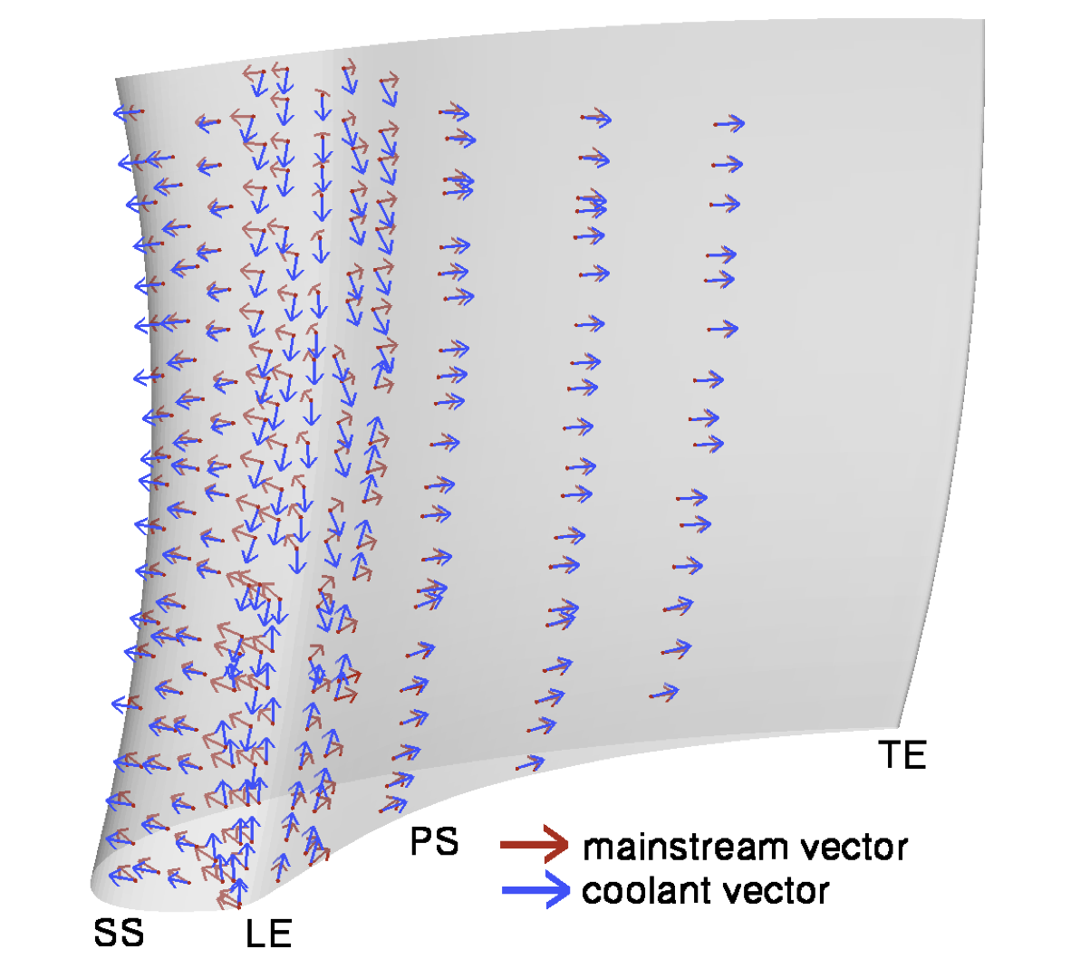
A methodology is presented to allow designers to estimate the penalty for turbine efficiency associated with film cooling. The approach is based on the control volume analysis of Hartsel and the entropy-based formulations of Young and Wilcock. The present work extends these techniques to include flow ejected at compound angles and uses three-dimensionalCFD to provide the mainstream flow properties. The method allows the loss contribution from each hole to be identified separately.
The proposed method is applied to an aeroengine highpressure turbine stage. It is found that, if the efficiency definition includes all irreversibilities, the penalty associated with film cooling would be 8.0%. However, if the pragmatic approach is adopted whereby the unavoidable entropy generated due to the equilibration of coolant and mainstream static temperatures is ignored, the efficiency penalty is 0.7%.
Finally, a series of case studies is used to quantify the impact of changes to the local mainstream flow direction and coolant ejection angle on the predicted turbine efficiency. It is shown, quantitatively, that reducing the angle between the directions of the coolant and mainstream flows offers the greatest potential for the designer to improve film cooled turbine efficiency.
Aerothermal Impact of the Interaction between Hub Leakage and Mainstream Flows in Highly-Loaded HP Turbine Blades
Popovic, I. and Hodson, H.P.
Paper GT2010-22311; Session MB-11-3; Monday 2:30pm-5:30pm
This paper describes experimental and numerical investigations of a highly-loaded rotor blade with leakage (purge) flow injection through an upstream overlapping seal. The effects of both leakage mass flow rates and swirl have been studied to examine their effects on the aerothermal performance.
As the leakage mass flow rate was increased, the loss generally increased. The increase in the losses was found to be non-linear with the three distinct regimes of leakagemainstream interaction being identified. The varying sensitivity of the losses to the leakage fraction was linked to the effects of the upstream potential field of the blade on a vortical structure originating from the outer part of the seal. This vortical structure affected the interaction between the leakage and mainstream flows as it grew to become the hub passage vortex. Very limited cooling was provided by the leakage flows. The coolant was mainly concentrated close to the suction surface in the front part of the rotor platform and on the blade suction surface in the path of the passage vortex. However, the regions benefiting from cooling were also characterized by higher values of the heat transfer coefficient. As a consequence, the net heat flux reduction was small and the leakage injection was thus deemed thermally neutral.
A Novel Technique for Measuring Stagnation Quantities and Gas Composition in High Temperature Flows
Massini, M., Miller, R.J., Hodson, H.P. and Collings, N.
Paper GT2010-22920; Session ThC-5-13; Thursday 2:30pm-5:30pm
A new probe has been developed to measure the time averaged stagnation temperature, stagnation pressure and gas composition. This probe can be used in the high temperature regions of gas turbines, including downstream of the combustor and in the first stages of the high pressure turbines, as well as in other environments.
The principal benefits of the new probe are that it overcomes the limitations of the standard methods that are used to measure temperature in high temperature environments and that it replaces three separate probes, for the three quantities mentioned above, with one single probe. A novel method of measuring temperature is used, which improves upon the accuracy of thermocouples and increases the temperature operating range.
The probe consists of a choked nozzle placed in the hot flow at the point of interest. The working principle is based on the theory that for a choked nozzle, there is a fixed relationship between the stagnation quantities, the gas characteristics and the mass flow rate through the nozzle. The probe has an aspirated phase, where the gas composition and the mass flow rate are measured and a stagnated phase, where the stagnation pressure is measured. The stagnation temperature is determined from the above quantities.
The operating principle has been proven valid through laboratory and rig tests. The probe has been successfully tested in a Rolls-Royce Viper engine up to 1000K and 2 bar and in a combustor rig up to 1800K and 4 bars. Measurements of stagnation temperature, stagnation pressure and gas compositions for these tests are presented in the paper and are compared with reference measurements. The accuracy of stagnation pressure and gas composition measurements is equal to the accuracy achievable with techniques that are commonly used in gas turbines. The estimated achievable accuracy of the aspirated probe in terms of temperature measurements is +/-0.6%, i.e. +/-10K at 1800K, which improves upon the accuracy of temperature measurements performed with standard thermocouples at the same temperatures, the uncertainty of which could be as high as +/-2%.
Aeromechanical Optimisation of a Winglet-Squealer Tip for an Axial Turbine
Zbigniew Schabowski, Howard Hodson, Davide Giacche, Bronwyn Power, Mark R. Stokes
Paper GT2010-23542; Session TA-27-6; Tuesday 8:00am-10:00am
The possibility of reducing the over tip leakage loss of unshrouded axial turbine rotors has been investigated in an experiment using a linear cascade of turbine blades and by using CFD. A numerical optimisation of a winglet-squealer geometry was performed. The optimisation involved the structural analysis alongside the CFD. Significant effects of the tip design on the tip gap flow pattern, loss generation and mechanical deformation under centrifugal loads were found.
The results of the optimisation process were verified by low speed cascade testing. The measurements showed that the optimised winglet-squealer design had a lower loss than the flat tip at all of the tested tip gaps. At the same time, it offered a 37% reduction in the rate of change of the aerodynamic loss with the tip gap size.
The optimised tip geometry was used to experimentally assess the effects of the opening of the tip cavity in the leading edge part of the blade and the inclination of the pressure side squealer from the radial direction. The opening of the cavity had a negligible effect on the aerodynamic performance of the cascade. The squealer lean resulted in a small reduction of the aerodynamic loss at all the tested tip gaps.
It was shown that a careful consideration of the mechanical aspects of the winglet is required during the design process. Mechanically unconstrained designs could result in unacceptable deformation of the winglet due to centrifugal loads. An example winglet geometry is presented that produced a similar aerodynamic loss to that of the optimised tip but had a much worse mechanical performance. The mechanisms leading to the reduction of the tip leakage loss were identified. Using this knowledge, a simple method for designing the tip geometry of a shroudless turbine rotor is proposed.
Numerical calculations indicated that the optimised low-speed winglet-squealer geometry maintained its aerodynamic superiority over the flat tip blade with the exit Mach number increased from 0.1 to 0.8.
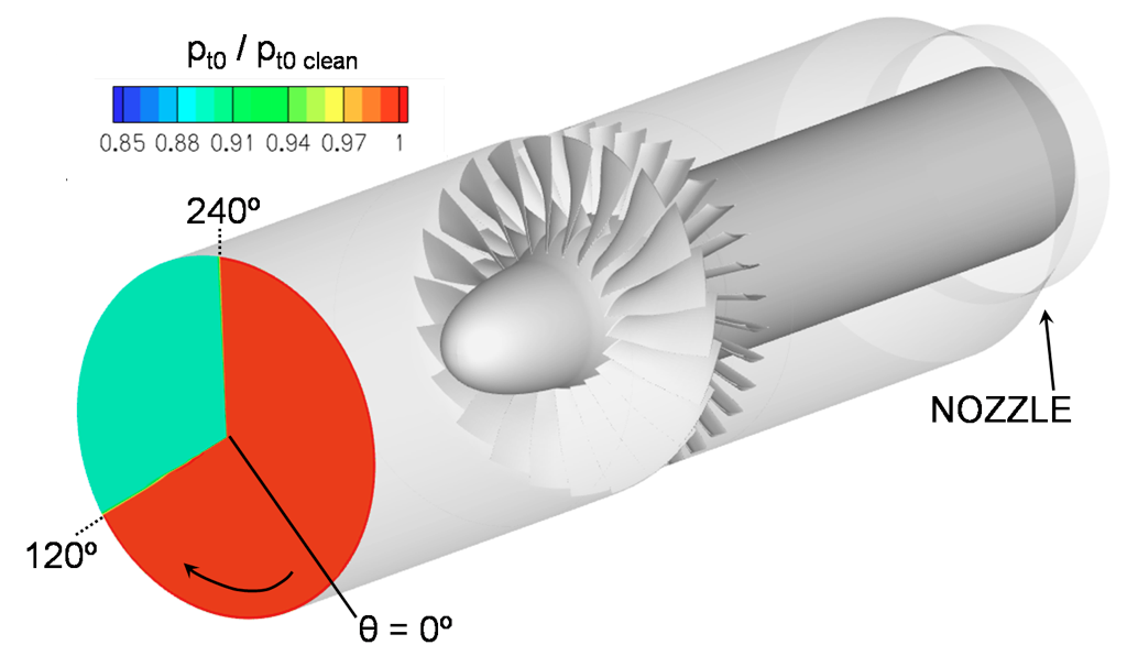
A Study of Fan-Distortion Interaction within the NASA Rotor-67 Transonic Stage
Jerez Fidalgo, V., Hall, C.A. and Colin, Y.
Paper GT2010-22914; Session FB-26-8; Friday 10:15am-12:15pm
The performance of a transonic fan operating within non-uniform inlet flow remains a key concern for the design and operability of a turbofan engine. This paper applies computational methods to improve the understanding of the interaction between a transonic fan and an inlet total pressure distortion. The test case studied is the NASA rotor 67 stage operating with a total pressure distortion covering a 120-degree sector of the inlet flow-field. Full-annulus, unsteady, three-dimensional CFD has been used to simulate the test rig installation and the full fan assembly operating with inlet distortion. Novel post-processing methods have been applied to extract the fan per-formance and features of the interaction between the fan and the non-uniform inflow. The results of the unsteady computa-tions agree well with the measurement data. The local operating condition of the fan at different positions around the annulus has been tracked and analysed, and this is shown to be highly dependent on the swirl and mass flow redistribution that the rotor induces ahead of it due to the incoming distortion. The upstream flow effects lead to a variation in work input that de-termines the distortion pattern seen downstream of the fan stage. In addition, the unsteady computations also reveal more complex flow-features downstream of the fan stage, which arise due to the three-dimensionality of the flow and unsteadiness.
Some Limitations of Turbomachinery CFD
John D. Denton
Paper GT2010-22540; Session WA-29-3; Wednesday 8:00am-10:00am
CFD is now an essential tool for the design of all types of turbomachinery. However, as engineers are exposed more and more to the results of CFD and less and less to experimental data there is a danger that they may not realise the limitations of CFD and so will view its predictions as more reliable than they really are and not question them sufficiently. This is particularly dangerous when CFD is use as part of an optimisation procedure. The objective of this paper is to try to expose some of the limitations of CFD as used for routine turbomachinery design.
CFD is not an exact science. Errors can arise from the following sources:
- Numerical errors due to finite difference approximations
- Modeling errors, where the true physics is not known or is too complex to model e.g. turbulence modeling
- Unknown boundary conditions, such as inlet pressure or temperature profiles
- Unknown geometry such as tip clearances or leading edge shapes
- Assumption of steady flow
Each of these sources of error is discussed and examples of the differences they can cause in the predictions are shown. Despite these limitations CFD remains an extremely valuable tool for turbomachinery design but it should be used on a comparative basis and not trusted to give quantitative predictions of performance.
Study of the Flow in a Vaneless Diffuser at Part Speed Operating Conditions
Hamid R Hazby, Liping Xu and Matthias Schleer
Paper GT2010-22605; Session WC-31-3; Wednesday 2:30pm-5:30pm
In this paper the evolution of the flow in the vaneless diffuser of a scaled turbocharger compressor has been investigated, using the steady-state viscous calculations. The predicted flow patterns are compared with the detailed LDA and probe measurements, acquired at different operating conditions. The numerical results are then analyzed further to obtain the understanding of the origins of the flow features, which are observed in the measurements.
It is shown that despite the complexity of the flow, the main flow features in the vaneless diffuser can be predicted at various operating conditions, using a simple mixing length turbulence model. It is also demonstrated that in the compressor studied, a vortical flow feature develops near the diffuser shroud at high flow coefficients. This flow feature is driven by strong pressure variations downstream of the impeller trailing edge present at high flow rates. At low flow coefficient conditions, where the static pressure gradient becomes almost radial in the vaneless diffuser, this feature disappears.