Demonstration of gyroscopic precession
In the early part of his lecture Laithwaite uses a Victorian gyroscope to demonstrate gyroscopic precession. Precession describes a change in the direction of the axis of a rotating object, so in this case a change in the spin axis of the gyroscope.
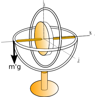
Laithwaite hangs weights from a Victorian gyroscope in order to demonstrate precession

Diagram of Victorian gyroscope
used by Laithwaite to demonstrate precession

When the weight is added to the gyroscope (with the rotor spinning) gyroscopic precession occurs. This precession is in a direction perpendicular to the direction that the weight force acts. The precession that occurs is demonstrated in the animation on the left which shows a view from above the gyroscope as it precesses (parts of the gyroscope such as the base are omitted for clarity)
Why does precession occur?
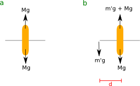
The weight that is hung of the gyroscope (represented by a cross on the diagram to the left) is offset from the center of mass of the gyroscope and stand. It is this offset of forces which causes precession.


The moment of momentum of the rotor is defined as
 where C is a
constant given by the principle
moment
of inertia about the k axis. From this formula it can be seen
that
the direction of the moment of momentum vector coincides with the
direction of spin of the rotor.
The gyroscope is mounted on a stand and so the center of the rotor is a fixed point therefore this can be simplified to

This result is key, the moment of momentum vector, h is changed a small amount in the direction of Q (the applied couple).
.

The direction of the couple and spin vectors can be calculated using the right hand screw rule. From this the direction of precession is obtained using the information that the moment of momentum and so spin axis is changed in the direction of the applied couple.
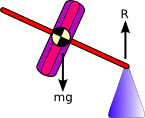
Precession of a toy gyroscope

 and
precession occurs about this point. The direction of
precession
is dependent on the direction of spin of the rotor.
Toy gyroscopes are easy to get hold of in most toy shops, so this can be tested and the direction of spin varied to see what happens to the direction of precession. The moment of momentum vector,h will always move in the direction of the applied couple.
Demonstrations of precession
Nutation
Another motion nutation can also be observed during precession, thus is a steady state motion of the bodies k axis about the K axis with constant angle between them, it is observed as a fast wobbling motion